

Subsystems fall into 3 categories. Please click on the headings below to move between the three categories.
Click here for a Decision table to determine the kits best suited to your students' needs.
To see prices, click here for the Technology Catalogue.
For more detailed information about each kit please refer to the individual kit's teaching unit. If the unit is not downloadable please contact us and we will email you a copy.
Gearboxes (assembled or unassembled)
Electronic Kits
Mechanical Kits
Gearboxes
Unassembled Gearboxes
Basic Gearbox and Motor Kit
Code: GBASIC
Click here for teaching unit
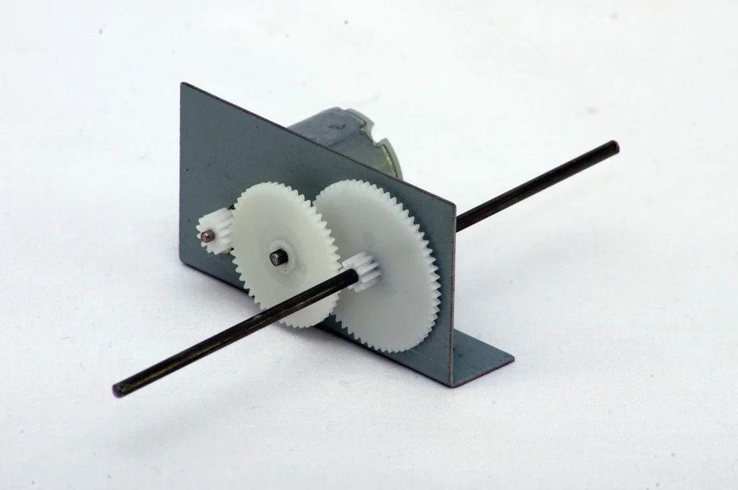
The BASIC GEARBOX and MOTOR KIT is a very versatile and easy to assemble gear box. The unit is compact and comparatively strong, and can be used in a many applications – anywhere where rotary motion is required. For example, it can be used in isolation (i.e. to drive or steer a model vehicle), it can have a gear fitted (to interface with other mechanisms), or it can drive a pulley and belt assembly. The gearbox can be used to drive a wheel or pulley through a single shaft, or the gearbox can be configured to drive two wheels through a longer double-sided configuration. This provides four possible configurations of the gearbox, and these are detailed below.

Intermediate Gearbox and Motor Kit
Code: GINTER
Click here for teaching unit
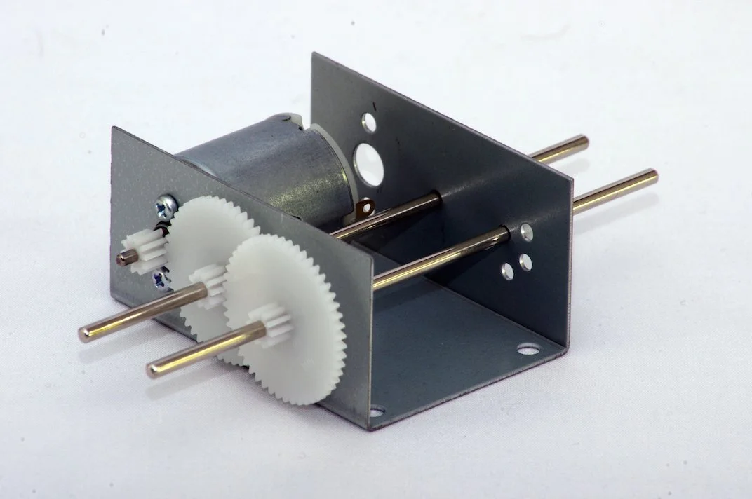
The INTERMEDIATE GEAR BOX kit provides a choice of 4 gear ratios. Before starting, the desired ratio must be determined, as this defines the parts to be used, and the assembly procedure. The gearbox can be used on its own, or as a "building block" for a motorised system or vehicle.

Gearbox and Motor/Generator Kit
Code: GRED
Click here for teaching unit
The GEARBOX & MOTOR/GENERATOR KIT provides electric power, through a 3 stage gearbox connected to a small DC generator. This can be turned by hand, connected to a water wheel, a windmill or whatever else the student decides upon.

Multi-ratio Gearbox Kit
Code: GMULTI (Ratio's 1:5, 1:25, 1:125, 1:625)
Click here for teaching unit overview
Code: GADVAN (Ratio's 1:5, 1:18, 1:64, 1:228)
Click here for teaching unit overview
The MULTI-RATIO GEARBOX kit provides a choice of 4 gear ratios to choose from. There are also two motor options available (which must be purchased separately). Before starting assembly, the desired motor option and the gear ratio must be selected, as this defines the parts to be used, the assembly side and the assembling procedure. This gearbox can be used with either the MOT17 motor or the high performance MOT30, these must be purchased separately.
Two Ratio Gearbox Kit
Code: GTWORKIT
Click here for teaching unit Overview
This TWO-RATIO GEARBOX provides a choice of 2 gear ratios.
The choice of ratios available at the “Output” shaft are:
· Single reduction (shaft A) = 1:5
· Double reduction (shaft B) = 1:25
This version is an unassembled kit that provides the parts to build one of the two options above. Before building you must choose which of the motors will be used.
Minimum order quantity for this kit: 50 units.
NOTE: The TWO RATIO GEARBOX kit with assembled gearbox has been discontinued.

Versatile Gearbox Kit - 6 Speed
Code: GVERS6
Click here for teaching unit overview
The VERSATILE GEARBOX KIT has a number of components supplied. These allow the maker to choose and assemble one of six possible gearbox ratios, according to the desired drive speed.
Shallow Gearbox Kit
Code: GSHALL
Click here for teaching unit
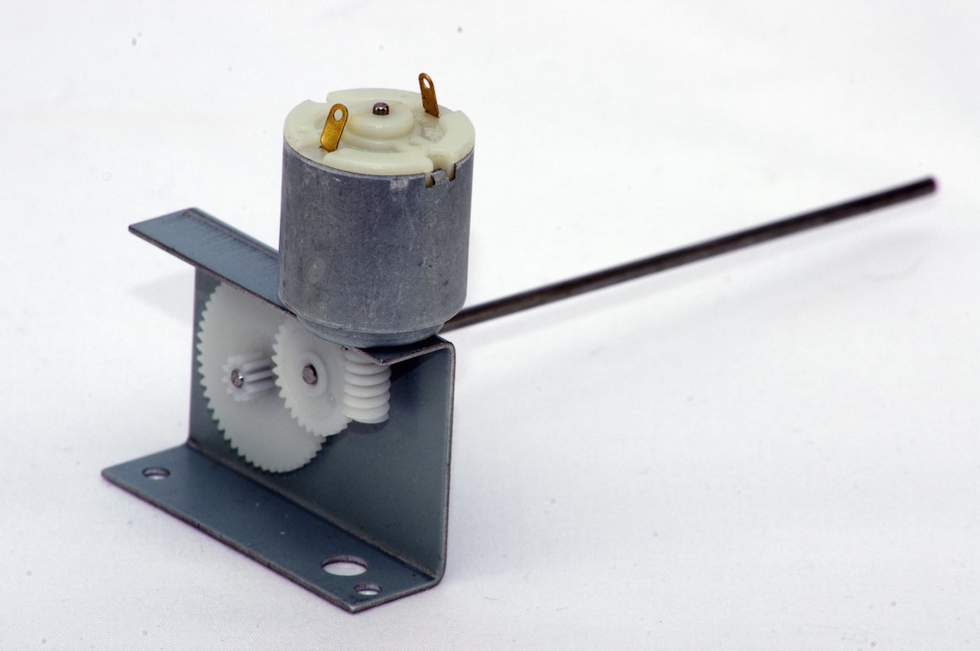
The SHALLOW GEAR BOX AND MOTOR kit is an easy to assemble gearbox, and provides a choice of 2 gears. The unit is compact and allows the designer to utilise narrow spaces. It can be used in many applications where rotary motion is required. For example, it can be used in isolation (to drive or steer a model vehicle), or as part of a system, (to drive a pulley and belt assembly). The gearbox can be used to drive, for example, one wheel or pulley through a single-sided shaft, or two wheels by using a longer shaft protruding through both sides.
Assembled Gearbox and motors

Four Ratio Gearbox
Codes (please specify variant required from list below when ordering):
GFOURA - 1:12,
GFOURB - 1:32,
GFOURC - 1:84,
GFOURD - 1:236

Click here for teaching unit
This pre-assembled Gearbox / Motor is available in 4 ratios. Its advantage is that later on any of the other ratios can be obtained by moving some of the gears. The axle shaft width is 150mm.
IMPORTANT: Ratio can only be changed a limited number of times with care, but cannot be changed once lubricated. It is better to work out the desired ratio before starting the project, to avoid the need to change gears later on.

Four Ratio Gearbox - Single sided
As per the above FOUR RATIO GEARBOXES , but the shaft projects only 1 way. The end of the shaft is approximately 11cm from the gearbox.
Codes (please specify variant required from list below when ordering):
GFOURSA - 1:12,
GFOURSB - 1:32,
GFOURSC - 1:84,
GFOURSD - 1:236
IMPORTANT: Ratio can only be changed a limited number of times with care, but cannot be changed once lubricated. It is better to work out the desired ratio before starting the project, to avoid the need to change gears later on.
Electronic Kits
Generator Output Monitor
Code: GOM
Click here for teaching unit
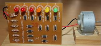
The GENERATOR OUTPUT MONITOR project allows the user to monitor a generator’s output. Graduated LEDs give an indication of this output. A small generator is included in the kit.

Infra-red controller unit - 6 Band
Code: IRCU with PCBIR6-A (Assembled PCBs)
Code: IRCU with PCBIR6-UN (Un -assembled PCBs)
The INFRARED CONTROL UNIT consists of the Transmitter and the Receiver assemblies (the PCBs with all their electronic components soldered in place), and all other parts required to operate the unit. The INFRARED CONTROL UNIT can transmit on six (6) bands, so that 6 different devices can be operated at the same time, by selecting different bands, using the band selection switch.
The Transmitter is used to transmit 6 different commands to the Receiver, which is mounted on a vehicle or whatever device you choose to make.
The IRCU is for indoor use only and will not operate outdoors. It can operate up to a distance of approximately 20 metres.

Motor Speed Controller
Code: MSC
Click here for teaching unit
This circuit allows the user to adjust the speed of a motor between a stopped state and up to full speed. The same system can be used with the General Output Monitor kit or as a light dimmer for a 6Volt bulb.

Radio Control Unit 2 Band (2-5 hours assembled) (5-10 hours unassembled)
Code: RCU with PCBRCRT-A (Assembled PCBs )
Code: RCU with PCBRCRT-UN (Unassembled PCBs) - (unassembled PCBs are currently out of stock)
Click here for teaching unit
The 27.145 MHz RADIO CONTROL UNIT (RC) consisting of the transmitter and the receiver PCB assemblies - enables you to control whatever device you are constructing. The transmitter PCB is used to transmit 3 commands to the receiver PCB, which is mounted on a vehicle or other device of your making. The radio transmission distance is up to 25 metres, and under favourable conditions it may be more.

Controller
Code: CONTROLLER
Click here for teaching unit
The CONTROLLER is a general purpose controller, and may be used control up to six small DC motors with simple position feedback. The central control element for the CONTROLLER is a Picaxe-40X microcontroller. Other devices may also be connected to the unused inputs and outputs. Suitable for many applications, such as the ROBOT ARM.

PICAXE08M2 Solar Panel Power Controller
Code: PICSPPC08M2
The PICAXE08M2 SOLAR PANEL POWER CONTROLLER controls a solar panel’s output voltage to its maximum power point voltage irrespective of load. This results in the transfer of all the available solar panel power to the load.
Depending on the load characteristics this circuit can provide a significant multiplication of the current available from the solar panel into the load.
For a motor this means increasing its torque, especially useful when a car is accelerating from a standing start. This feature also allows a motor to start and operate at a much lower light intensity than is possible with the motor directly connected to the solar panel.
The unit automatically sets the appropriate control voltage on start up.
While it was specifically designed to operate with a Scorpio No. 26 Solar panel it will operate with any solar panel that has an open circuit voltage between 7.0 volts and 10.0 volts and a short circuit current between 0.1 amp and 1.0 amp.
PLEASE NOTE: The PICSPPC08M2 is supplied with a blank PICAXE chip that requires programming and requires a PICAXE download cable (Code: PICUCAB). Pre-programmed PICAXE chips are also available upon request. Please specify whether you require a blank or pre-programmed chip when ordering.

Solar Panel Power Controller Low Voltage Unit - VOC 6.5-12V (3-5 hours)
Code: SPPCL
Click here for teaching unit
The SOLAR PANEL POWER CONTROLLER (SPPC) multiplies the solar panel’s starting current for motors. Normally, powering an electric motor directly from a solar panel can be quite inefficient, especially during start up and at low motor speeds. The SPPC allows the motor to start and operate at a much lower light intensity than is possible with the motor directly connected to the solar panel. This SPPC circuit holds the output of the solar panel at its maximum power voltage point. Thus it is able to substantially boost the starting current available to the motor. NOTE: This circuit regulates the input voltage rather than the output voltage. The SPPC will work with any solar panel or combination of solar panels whose Voltage Open Circuit (VOC) voltage is between 6.5 and 12 volts (a rated 12V panel at VOC will be higher than 12V). Energy consumption by the circuit is 0.04 W (approximately). The SPPC’s weight is approximately 45 grams (including the inductor).
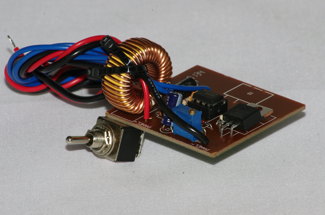
Solar Panel Power Controller Standard Voltage Unit - VOC 13-23V (3-5 hours)
Code: SPPCS
Click here for teaching unit
The SOLAR PANEL POWER CONTROLLER (SPPC) multiplies the solar panel’s starting current for motors. Normally, powering an electric motor directly from a solar panel can be quite inefficient, especially during start up and at low motor speeds. The SPPC allows the motor to start and operate at a much lower light intensity than is possible with the motor directly connected to the solar panel. This SPPC circuit holds the output of the solar panel at its maximum power voltage point. Thus it is able to substantially boost the starting current available to the motor. NOTE: This circuit regulates the input voltage rather than the output voltage. The SPPC will work with any solar panel or combination of solar panels whose Voltage Open Circuit (VOC) voltage is between 13 and 23 volts (a rated 12V panel at VOC will be higher than 12V). Energy consumption by the circuit is 0.04 W (approximately). The SPPC’s weight is approximately 45 grams (including the inductor).

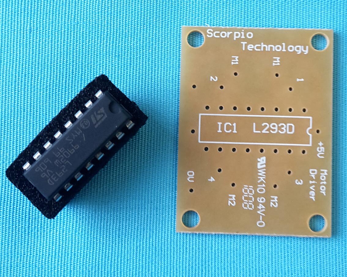

Reverse PCB Kit
Code: REVPCB
This kit provides all the components needed to make and mount a reversing PCB to interface with PAT’S MICROCONTROLLER . It consists of the PCB, a L293 motor driver, a 16 pin IC socket, 2 PCB spacers and nuts and bolts.
NOTE: The Robot Buggy (Code: BUGGY) has this kit included.
PCB-Reverse and IC L293MC (Set)
Code: REVDRIVE
These 2 components together (a small reversing PCB and the L293 motor driver) allow you to add a reversing function to PAT’S MICROCONTROLLER, for use with the BUGGY2WD.
NOTE: The Robot Buggy (Code: BUGGY) has the REVPCB kit included.
OLED Module
Code: OLED
Once you have seen an OLED display in use you will never want to use an LCD again!
OLED has a much brighter display, much better viewing angle and lower current consumption than backlit LCDs means that OLEDs are set to become the new LCDs!
The Serial OLED module allows PICAXE projects to display messages on a yellow on black OLED.
· Uses a pre-programmed PICAXE 18M2 chip to provide control of the screen.
· Interface via a single serial line
Can be connected to PAT’S MICROCONTROLLER to extend the possible usages.
Mechanical KITS

Front Wheel and Steering Linkage
Code: FRONT
Click here for teaching unit
Front wheel and steering linkage for a vehicle.

Faulhaber Motor Mounting Kit
Code: FAUMMK
Click here for teaching unit
The FAULHABER MOTOR MOUNTING KIT provides the parts (brackets, screws, nuts and bolts) to assemble an adjustable mount for a Faulhaber 2232 motor, which can be attached to a chassis or body.
In addition this kit can be used with the AXLE BRACKET KIT to attach the motor to a Carbon fibre tube.

The Axle bracket Kit
Code: AXBKTK
Click here for teaching unit
The AXLE BRACKET KIT provides the basic parts (axle brackets, nuts and bolts) to assemble 6mm carbon fibre tubes into a rectangle. This then forms the base of a Solar car.

SM403 Motor Mounting Kit
Code: SM403MMK
The SM403 MOUNTING KIT is used to attach the motor mounting bracket and the motor to one Carbon fibre tube. This kit provides the parts (brackets, screws, nuts and bolts) to assemble a SM403 motor to a chassis. Adjustment is by moving the motor up or down, allowing different gears to be used.
(Photo illustrates the SM403MOTK which is the SM403MMK with the SM403 motor. This kit is also available from Scorpio Technology).